Modern engines rely heavily on electronic sensors to maintain precision and efficiency. One such critical component is the Crankshaft Position Sensor. Without this sensor, the engine’s timing would be off, causing poor performance or complete engine failure.
In this article, you will learn what a crankshaft sensor is, how it works, where it is located, what the common signs of failure are, and how to diagnose or replace it.
What is a Crankshaft Position Sensor?
A crankshaft position sensor is an electronic device used in internal combustion engines to monitor the position and rotational speed (RPM) of the crankshaft. This information is sent to the engine’s control unit (ECU), which uses it to control vital functions such as fuel injection and ignition timing.
Without accurate input from this sensor, the engine would not know when to fire the spark plugs or inject fuel, leading to performance issues or engine failure. It plays a key role in ensuring smooth engine operation, better fuel efficiency, and reduced emissions.
What Does a Crankshaft Position Sensor Do?
The crankshaft position sensor is a critical engine component that monitors the position and rotational speed of the crankshaft. This information is sent to the engine control unit (ECU), which uses it to determine the correct timing of fuel injection and ignition.
Without a properly functioning crankshaft sensor, the engine may fail to start, stall, or run inefficiently. It is essential for maintaining smooth engine operation, performance, and fuel economy.
- Measures crankshaft position and RPM
- Sends data to the ECU for timing adjustments
- Helps control ignition and fuel injection
- Ensures proper engine synchronization
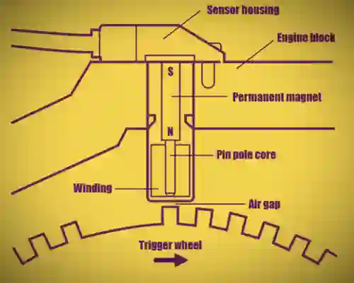
Crankshaft Position Sensor Diagram
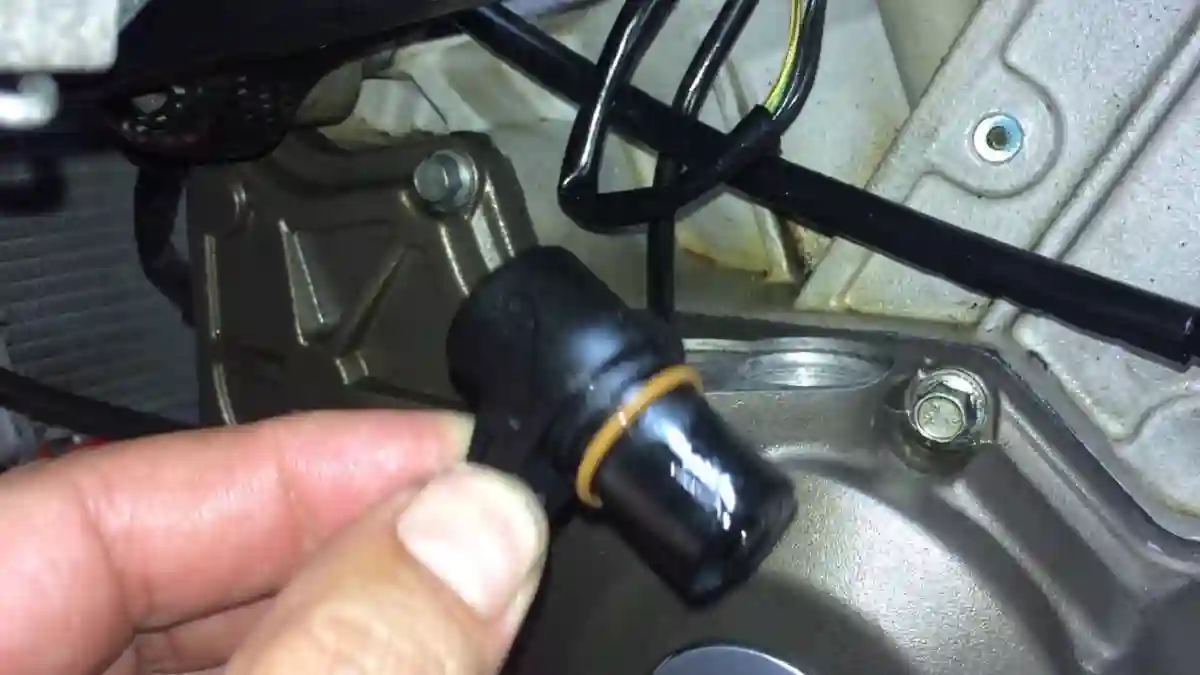
Crankshaft Sensor Location
The location of the crankshaft sensor varies depending on engine design but typically falls into one of these categories:
- Front of the engine (timing cover) – Near the crankshaft pulley or harmonic balancer.
- Rear of the engine (flywheel side) – Mounted through the bell housing, detecting the flywheel teeth.
- Side of the engine block – Usually near the crankshaft’s mid-section.
Working Principle of Crankshaft Position Sensor
There are primarily two types of crankshaft position sensors based on their working principles:
#1. Inductive (Magnetic) Sensor
- Made up of a permanent magnet, coil, and pole piece.
- As the teeth of the tone ring pass the sensor, a voltage pulse is induced.
- This alternating current (AC) signal varies in frequency and amplitude depending on engine speed.
#2. Hall-Effect Sensor
- Works on the Hall effect principle using a semiconductor chip.
- Produces a digital square wave signal (on/off pulses).
- Offers higher precision, stable at low speeds, and works even during engine cranking.
#3. Magneto-Resistive (MRE) Sensor (Advanced)
- Uses magnetic resistance to detect changes in magnetic fields.
- Highly accurate and immune to noise or temperature variations.
The ECU Processes This Information To:
- Trigger fuel injectors at the right moment
- Fire spark plugs precisely during compression stroke
- Control variable valve timing (in advanced engines)
Symptoms of a Bad Crankshaft Position Sensor
Some symptoms may start subtly, while others can appear suddenly and severely affect vehicle performance. Below are the most common and noticeable signs of a faulty crankshaft position sensor:
#1. Check Engine Light (CEL)
One of the earliest and most common indicators is the illumination of the check engine light on the dashboard. When the sensor sends irregular or no signal to the ECU, the system logs a trouble code, such as P0335, related to crankshaft signal issues. This warning light may stay on continuously or blink intermittently, depending on the severity of the issue.
#2. Hard Starting or No Start Condition
A failing crankshaft sensor may cause the engine to crank for an extended period before starting, or not start at all. That’s because without crankshaft position data, the ECU is unable to deliver spark and fuel at the correct time. In some cases, the engine may only start after multiple attempts or fail completely, especially when the engine is hot.
#3. Engine Stalling
Another common symptom is intermittent engine stalling. The engine might run fine for a few minutes and then suddenly shut off without warning.
This usually happens when the sensor signal is lost momentarily while driving or idling. A completely dead sensor may cause the engine to stall and not restart until it cools down or the issue is resolved.
#4. Engine Misfires
The crankshaft sensor plays a critical role in engine timing. If it sends incorrect signals, the spark plugs may fire at the wrong time, causing the engine to misfire.
You may feel jerking, hesitation, or uneven power delivery, especially when accelerating or climbing hills. Persistent misfiring can also damage the catalytic converter over time.
#5. Poor Acceleration
If the ECU doesn’t receive proper RPM and position data, it can’t adjust the fuel mixture or ignition timing correctly. As a result, the vehicle may feel sluggish, hesitate when you press the gas pedal, or lack power during acceleration. This is particularly noticeable when merging onto highways or overtaking other vehicles.
#6. Rough Idle
When idling, a faulty sensor can cause the engine to shake or vibrate due to unstable RPM. The idle speed may fluctuate, or the engine may sound rough and uneven. In severe cases, the engine might stall while idling at traffic signals or stop signs.
#7. Reduced Fuel Efficiency
Poor timing caused by a failing sensor often results in incomplete combustion of the air-fuel mixture. This can lead to increased fuel consumption, meaning you’ll notice that your car is using more fuel than usual for the same driving distance. Over time, this can become an expensive problem if not fixed.
#8. Vibrations or Unusual Engine Sounds
Engine misfires or improper timing can cause knocking, pinging, or tapping sounds, especially under load or acceleration.
In some cases, the engine may even shake excessively, making the vehicle feel unstable or noisy. These vibrations are usually more noticeable at low RPM or while idling.
Additional Signs
- Sudden loss of power while driving
- Engine enters “limp mode” to protect itself
- Overheating due to inefficient combustion
- Excessive exhaust smoke, especially black smoke from rich fuel mixture
Causes of Crankshaft Position Sensor Failure
Understanding what causes this sensor to go bad can help prevent future issues and keep your engine running smoothly. Below are the most common causes of crankshaft sensor failure:
#1. Heat Damage
The crankshaft sensor is often located near the engine block or exhaust system, areas that generate high heat. Continuous exposure to extreme temperatures can degrade the sensor’s internal components, especially in poorly ventilated engine bays or vehicles that frequently overheat. This thermal stress may lead to intermittent signal loss or complete failure.
#2. Oil Leaks or Fluid Contamination
Oil leaking from the crankshaft seal, valve cover gasket, or other engine components can seep onto the sensor or its electrical connector.
Over time, oil, coolant, or water can contaminate the sensor tip or cause short circuits, disrupting its ability to detect the crankshaft’s movement accurately.
#3. Wiring Issues or Corrosion
Damaged wiring, frayed insulation, or corroded connectors can interrupt the flow of electrical signals between the sensor and the ECU.
Exposure to moisture, road salt, or dirt can accelerate corrosion. In some cases, a loose plug or bent pin in the connector can cause intermittent sensor readings or total failure.
#4. Physical Damage
The sensor can be damaged during engine repairs, accidental impact, or incorrect installation. A cracked housing, broken mounting tab, or misaligned sensor can cause improper air gap between the sensor and tone ring, preventing accurate signal generation. Physical impact from road debris can also harm sensors located in vulnerable positions.
#5. Faulty Reluctor/Tone Ring
The sensor relies on a toothed reluctor wheel or tone ring attached to the crankshaft to generate signal pulses. If this ring becomes damaged, bent, cracked, or dirty, it can cause the sensor to miss teeth or send inaccurate signals. Missing or worn teeth may lead to poor signal recognition by the ECU.
#6. Electrical Overload or Short Circuit
Power surges, faulty grounding, or issues with other electrical components in the engine management system can overload the sensor. An unstable voltage supply or a short circuit in the wiring harness can burn out the internal electronics of the sensor.
#7. Poor Manufacturing Quality or Defective Parts
Low-quality aftermarket sensors may not meet OEM standards. These can fail prematurely due to cheap materials, inaccurate calibration, or poor assembly. Even new sensors can be defective right out of the box if not sourced from a reliable brand.
#8. Wear and Tear (Age-Related Failure)
Over time, the sensor’s components simply wear out. Prolonged exposure to vibrations, temperature changes, and mechanical stress gradually reduces its performance. Most sensors last 100,000 to 150,000 km, but failure can occur sooner under harsh conditions.
#9. Incorrect Installation
Improper installation, such as overtightening bolts, incorrect sensor gap, or plugging into the wrong connector, can lead to signal issues. Always follow manufacturer torque specs and gap recommendations when replacing the sensor.
Tip for Prevention:
- Keep the engine bay clean and dry.
- Repair oil leaks promptly.
- Use only OEM or high-quality aftermarket sensors.
- Regularly inspect sensor wiring during routine maintenance.
- Avoid overheating the engine to reduce thermal stress.
Diagnosing a Faulty Crankshaft Position Sensor
When your vehicle begins showing signs like hard starting, engine stalling, or misfires, a faulty crankshaft position sensor (CKP) could be to blame.
Accurate diagnosis is important before replacing the sensor, as similar symptoms can also be caused by ignition coils, camshaft sensors, or fuel issues. Below are the key steps to properly diagnose a crankshaft sensor failure:
#1. Check for Trouble Codes (Using OBD-II Scanner)
The first and most efficient step in diagnosing a CKP sensor issue is to scan the vehicle’s ECU for diagnostic trouble codes (DTCs) using an OBD-II scanner.
Look for any of the following common crankshaft sensor-related codes:
- P0335 – Crankshaft Position Sensor “A” Circuit Malfunction
- P0336 – Crankshaft Position Sensor “A” Range/Performance
- P0337 – Crankshaft Position Sensor “A” Circuit Low Input
- P0338 – Crankshaft Position Sensor “A” Circuit High Input
- P0339 – Crankshaft Position Sensor “A” Intermittent
These codes confirm that the ECU is either receiving incorrect signals or no signal at all from the crankshaft sensor.
Tip: Some basic scan tools only show codes but not live data. For deeper diagnostics, use a scanner that shows real-time RPM and signal values.
#2. Visual Inspection
After retrieving codes, perform a thorough visual check of the sensor and surrounding components. You may be able to spot the issue without advanced tools.
- Damaged or broken wires leading to the sensor
- Loose, corroded, or bent pins in the connector plug
- Oil, dirt, or debris on the sensor tip — common if there’s an oil leak nearby
- Cracks or physical damage on the sensor body
- Loose or missing mounting bolts, which can throw off alignment and air gap
Also inspect the reluctor ring or tone wheel for any missing, damaged, or bent teeth that could cause irregular signals.
#3. Multimeter Test (Sensor Output Test)
A multimeter can help you test whether the sensor is generating an appropriate electrical signal.
For Magnetic (Inductive) Sensors
These sensors generate an AC voltage signal as the crankshaft rotates.
- Disconnect the sensor harness.
- Set your multimeter to AC voltage mode.
- Connect the leads to the sensor terminals.
- Crank the engine (have someone turn the key while you watch the reading).
You should see a small but consistent AC voltage output (typically between 0.5V and 1.5V depending on RPM). If no voltage is present during cranking, the sensor is likely faulty.
For Hall-Effect Sensors
These generate a digital square-wave signal using DC voltage.
- Turn the multimeter to DC voltage.
- With the sensor connected, back-probe the signal wire (usually the middle pin).
- Have someone crank the engine.
You should see voltage switching rapidly between 0V and 5V as the teeth of the reluctor ring pass by. No voltage or constant 0V/5V means the sensor is likely bad or not receiving proper power.
Pro Tip: Also test for proper 5V reference and good ground on the other two wires.
#4. Oscilloscope Test (Advanced Method)
An oscilloscope provides the most accurate way to test crankshaft sensor operation by showing the real-time waveform of the signal being sent to the ECU.
- Visualize the signal pattern (waveform should be consistent and evenly spaced)
- Detect intermittent drops, distortions, or missing pulses
- Verify the presence of missing teeth (used for TDC detection)
Healthy crankshaft sensor waveforms are consistent in amplitude and frequency. Any signal noise, irregular gaps, or distortion may indicate a sensor or wiring fault.
Although oscilloscopes are typically used in professional garages, they are invaluable for pinpoint diagnostics, especially when symptoms are intermittent.
How to Replace a Crankshaft Position Sensor
Replacing a crankshaft position sensor (CKP sensor) is a manageable task for most DIYers with basic mechanical skills and tools. It typically takes 30 to 60 minutes, depending on the sensor’s location in your vehicle. Before beginning, ensure the engine is cool and you have the necessary tools ready.
Tools Needed:
- Basic socket set (metric or standard, depending on your car)
- Screwdriver (flathead or Phillips)
- Jack and jack stands (if the sensor is located underneath)
- Clean rag or shop towel
- Multimeter (for optional pre-testing)
- Torque wrench (recommended for precise bolt tightening)
- OBD-II scanner (to clear trouble codes)
- New crankshaft position sensor (OEM or quality aftermarket)
#1. Disconnect the Battery
Safety first, always disconnect the negative terminal of the battery to prevent any accidental shorts or electrical surges during sensor removal or installation.
#2. Locate the Sensor
Refer to your vehicle’s repair manual or follow the wiring harness from the engine’s ECU to the sensor. The crankshaft sensor is usually mounted:
- Near the crank pulley (front of engine)
- Beside the flywheel housing (rear of engine) Or along the engine block near the oil pan
- Some vehicles may require removing underbody shields or engine covers for access.
#3. Unplug the Electrical Connector
Once you have access to the sensor, carefully unplug the electrical connector. Be gentle — do not pull on the wires. Use a small flathead screwdriver if needed to press the release tab.
#4. Remove the Mounting Bolts
Use a socket wrench to remove the bolts or screws securing the sensor to the engine. Most sensors are held by a single bolt, but some may have two. Keep these bolts in a safe place, as you’ll reuse them.
#5. Gently Remove the Sensor
After removing the bolt(s), gently pull the sensor straight out. If it’s stuck due to dirt or corrosion, use a soft twisting motion. Avoid using force or prying tools that might damage the sensor seat or surrounding components.
#6. Clean the Sensor Mounting Area
Before installing the new sensor, clean the mounting surface using a clean rag to remove dirt, oil, or debris. This ensures a snug fit and accurate air gap between the sensor and reluctor wheel.
#7. Install the New Sensor
Place the new sensor into the mounting hole, aligning it with the reluctor ring. If your sensor requires a specific air gap (usually 0.5 mm to 1 mm), refer to your vehicle’s service manual.
Some sensors are self-adjusting, while others may need a spacer or shim. Tighten the mounting bolt(s) to the manufacturer’s torque specification — overtightening can damage the sensor or block.
#8. Reconnect the Electrical Connector
Plug the sensor harness back in until it clicks into place. Double-check for a firm connection and inspect for any wire damage.
#9. Reconnect the Battery
Reconnect the negative battery terminal and ensure it’s secure.
#10. Clear Stored Fault Codes
Use an OBD-II scanner to clear any stored crankshaft-related fault codes (like P0335 or P0336). This step ensures the ECU recognizes the new sensor and resets the check engine light.
#11. Test Drive the Vehicle
Start the engine and let it idle for a few minutes. Observe the following:
- Smooth idle and engine response
- No check engine light
- No unusual noises or vibrations
Take the vehicle for a short test drive and monitor performance. If the engine runs smoothly and the CEL stays off, the replacement was successful.
Extra Tips for a Successful Replacement
- Use OEM or high-quality aftermarket sensors to ensure reliability and compatibility.
- Avoid touching the sensor tip with oily hands; clean sensors work more accurately.
- Always verify the air gap if your vehicle requires manual adjustment.
If the problem persists after replacement, double-check the wiring harness and reluctor wheel for damage.
Final Thoughts
The crankshaft position sensor might be a small component, but its role is massive in ensuring that your engine runs efficiently, reliably, and safely. Ignoring symptoms of a faulty sensor can lead to major drivability problems.
The good news? It’s a relatively affordable part, and with basic tools and patience, you can diagnose and replace it yourself in many cases.
FAQs
Here are some frequently asked questions (FAQs) about the crankshaft position sensor to help you better understand its role, issues, and replacement.
Q. What does a crankshaft position sensor do?
The crankshaft position sensor monitors the position and rotational speed (RPM) of the crankshaft. It sends this data to the engine control unit (ECU), which uses it to control ignition timing and fuel injection. Without this sensor, the engine would not run efficiently or may not start at all.
Q. Can I drive with a bad crankshaft position sensor?
It is not recommended. While you might be able to drive short distances with a failing sensor, it can cause the engine to stall suddenly or not restart, putting you at risk. Long-term driving with this issue can also damage the catalytic converter or other engine components.
Q. How much does it cost to replace a crankshaft position sensor?
- Sensor part cost: $25 to $100
- Labor cost: $50 to $150
- In total, professional replacement usually ranges from $75 to $250. DIY replacement can save on labor if you have the tools and experience.
Q. How long does a crankshaft position sensor last?
Under normal conditions, a crankshaft sensor can last 100,000 to 150,000 kilometers (or 60,000 to 100,000 miles). However, harsh engine environments, overheating, or electrical faults can shorten its lifespan.
Q. Is it necessary to reset the ECU after replacing the sensor?
Yes, it’s recommended to use an OBD-II scanner to clear any stored error codes after replacing the sensor. This allows the ECU to recalibrate with the new sensor and ensures the check engine light does not return due to old fault codes.